Friday, January 31, 2025

WALL MOUNTING A BIG SCREEN TV

      Thanks for joining us today here at Fresh's Workshop. If you are a first-time visitor, WELCOME. If you have been here before, THANKS for coming back.

This is the spot where we build and repair all kinds of cool stuff, along with making a ton of saw dust. (Man Glitter.)

Last time in the Workshop, we worked on a Digital Clock for the Nightstand  (Click on the link to see that episode) 

Before we begin today's project, let's take a moment and talk about shop safety:

Be sure to read, understand and follow all of the safety rules that come with your power tools. Knowing how to use your power tools properly will greatly reduce the risk of personal injury. And remember this, there is no greater safety rule than to wear safety glasses.

Today, we are installing a large-screen TV on our bedroom wall. This will free up space on the dresser for the VCR/DVD player and network switch. Indeed, I still possess a VCR and take pleasure in watching DVDs. 
All wires and cables will be neatly concealed within the wall for a clean presentation. This includes the power cable, HDMI cable for the Roku and VGA cables for the VCR/DVD player. An additional HDMI cable will also be installed for the Blu-ray player.

First, we need the wall mount:

And a couple of boxes to hide all of the wires:

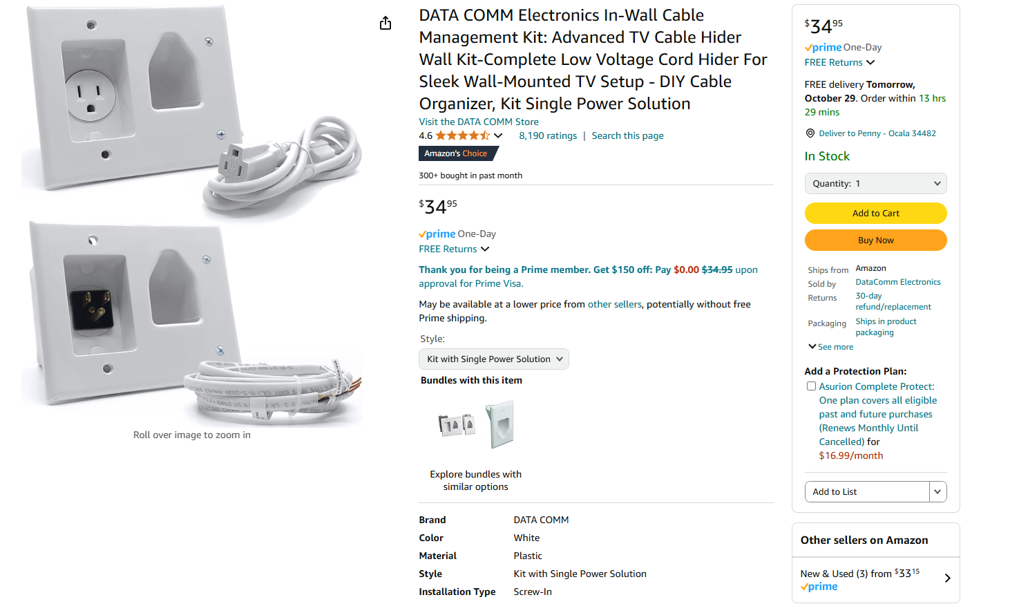
I have made these purchases; however, your requirements may differ. Amazon provides a wide range of options, or you may also consider exploring the selections at your local Home Center.

So, let's take a look at the wall.
I applied painter's tape along the wall to mark the location of the studs.

Ensure that you install your mount into a stud Avoid using any specialized drywall mounts. Use studs exclusively.

If you have a concrete wall, refer to your instructions for the appropriate mounting procedure.

We recently replaced our aquarium with the CD bookcase, as I preferred not to have the aquarium near our workspace. Consequently, the fish tank was relocated to a different area of the room.

The initial step involves locating the wall studs. Assuming the house was constructed correctly, there should be a stud to the left of the switch box, within the CD shelves. Another stud is expected to be found 16 inches from the first.

From our project "BOOKCASE MOUNTING AROUND A WALL PLATE," we discovered that there was a stud just to the left of the switch and fan box. So, let's take some measurements and use our stud finder.
By utilizing painter's tape and a stud finder, I can accurately mark the of each stud..
Indicate each side of the stud, ensuring that you secure your mount in the center of each stud.

The most important step in the process is to R.T.F.M. (Read the frickin' manual) for your mount. Follow ALL of the safety tips they list. 


Now that we have the studs marked, I taped up the mounting template on the wall.
Turning to the TV, I mounted the TV portion of the mount according to the instructions. Remember them? They came in the box. READ IT. The instructions, not the box.
These brackets are secured to the back of the TV.

By placing the wall mount on the back of the TV, I can determine where the top and side of the TV will be positioned on the wall. Ensure that there is sufficient space.


With our distances verified, we drill a hole into the studs, using the template as a guide. A level is also useful.


Four neatly drilled holes are now prepared for the mount. Position the mount on the wall and secure it with A lag screw. I tightened one screw firmly, adjusted the unit to make it level, and then secured the remaining screws.


The mount for your TV is now ready.

However, we still to conceal the wires.

The kit I demonstrated earlier will be installed adjacent to the mount.

It includes a cut-out template which I used to mark the location on the wall.

Using my saw, I cut out the hole. I had drilled a hole as I intended to use my drywall hand saw. However, I couldn't locate it, so used my cut-out saw instead.
Then I wired the included Romex to the outlet. DO NOT use an extension cord for this. Use the supplied Romex. It is against the Electrical Code to run extension cords through a wall.

Now I can insert the box into the hole.
And install the box according to the directions.
Now we do the same thing at the floor.
Run the Video wires through the top box to the floor level.
That's enough for today, let's take a break.

So, I finished the bottom just like I did the top. 

The only task remaining is to hang the TV, which is definitely not a one-person job. It's crucial to have assistance; attempting it solo could be a recipe for disaster. So, find a friend to lend a hand, regardless of their alma mater—even if it's Auburn.
Sorry no picture of the hanging up of the TV, all you would have seen is two butt cracks.

So, let's hook up all the wires. And Bob's Your Uncle.

Now we can lie in bed and watch our favorite TV program at the proper height, with access to the VCR/DVD/ROKU player. 
And those wires at the lower right? They are coming out on another episode of Fresh's Workshop. (I hate climbing around small attics.)
Coming up next in Fresh's Workshop, I think we'll be working on cabinets for the Digital Clocks, and we'll finish up the Audio Equalizer. Hopefully the weather will warm us up, so we can get back into the wood shop. But first, it will be shop 'clean up' time.

Be sure to visit some of my other blogs:

AROUND THE KITCHEN  - SEE WHAT I COOK

BRIARWOOD - YOU CAN READ MY NOVELS

AUDIO CONSOLE - WHERE I AM BUILDING AN AUDIO MIXER

DISCLAIMER The information contained here is for ENTERTAINMENT purposes only. Working with woodworking tools can be dangerous. The user of these tools should have a basic knowledge of woodworking and be familiar with the proper use and safety precautions associated with these tools. Always wear appropriate personal protective equipment, such as safety glasses, ear protection, and a dust mask. Always use the tool in accordance with the manufacturer's instructions and guidelines. Always maintain a safe and organized work area.
GOD SPEED, MOTHER NATURE


Saturday, January 25, 2025

DIGITAL CLOCK FOR THE BEDROOM - - PART ONE (THE CLOCK)

Thank you for joining us today at Fresh's Workshop. If this is your first visit, welcome! If you're returning, we appreciate your continued support.

This is the spot where we build and repair all kinds of cool stuff, along with making a ton of saw dust. (Man Glitter.)

During our last session in the Workshop, we worked on a Lazy Susan for the kitchen.

To see that episode, just clicky clicky here:
 
Before we begin today's project, let's take a moment and talk about shop safety:
Be sure to read, understand and follow all of the safety rules that come with your power tools. Knowing how to use your power tools properly will greatly reduce the risk of personal injury. And remember this, there is no greater safety rule than to wear safety glasses.

Today, we return to the Electronics Shop to work on a digital clock for the nightstand. I wanted a larger one that is easy to see without my glasses.

I have been working on digital clocks for a couple years as I develop a 6-channel audio mixer with a resettable timer. I also wanted to design two clocks side by side for the radio room, one set to EST and the other to GMT.

I had a couple of boards left over from the Ham Radio Clock build, I thought I would put a unit together for the bedroom. The boards had a couple of traces missing, so I had to run a few jumpers to make it work. I also added a couple of 'pull down" resistors as well. I did not want to have to reorder five boards. (My supplier has a five-board minimum order.)

This clock will NOT have an alarm function. I'm retired, so I don't need an alarm.

For all the electronic info, hop on over to my Audio Mixer blog, we have an eight or nine-part blog that is more detailed than what I will have here. 

This will be more about the building of the clock and a cabinet rather than the design of the clock.

But to perk your interest, here is the schematic. First, the main clock board.

A controller.
And a power supply. +10-15 V in, 5V out.
Regarding the circuit boards, there is a main board, as well as a controller and power supply board.


WHOOPS, I forgot about the Display Board.
This is designed to feed a 1-second pulse to either LEDs or the decimal point on the displays. I always use the small LEDs to display the seconds. You can choose either function via JP1. The display uses 1-inch 7-segment displays, which are perfect for our needs.

Before we commence construction, I would like to clarify a few points. Although I could have utilized more advanced technology to achieve the same result, I opted for a design that is straightforward to understand and repair in case of malfunctions. Additionally, the process was enjoyable and kept me occupied during the evenings.
Let us proceed. We have boards and the components. We will begin with the displays. You will observe that I frequently use "sockets" in my electronic work. This allows for easy replacement of parts if necessary.

I utilize 40-pin sockets for the displays and the LED seconds displays. Simply cut off the desired number of pins.

I place the pins on the display and insert it into the board. I tape it down, turn it over, and solder the pins place. I repeat this process for each segment. This keeps everything in proper alignment.


Repeat with the jumper and the IDC cable sockets.

And the resistors.
And the display board is complete.
Yes, I did realize that one of the displays was upside down!
Now that the display is complete, we will proceed to the clock. We will use our bench power supply to run the clock until we create the power supply and cabinet.
I always start with the power sections. I install the filter capacitor, LED resistors, and LED. Then I power it up and ensure it is functioning properly. Next, I move on to the counter section, which generates the 1 Hz pulse to make the clock count. The heart of that section is the 4060-chip counter and a crystal. Be careful when soldering the crystal. Ensure you use a clamp as a heat sink to avoid burning out the crystal. I learned this the hard way.
Install all the 4060 and the 4013 components as well. Now you can check with power. Yep, it counts.


The far-right LED indicates the Power (5V). The two LEDs on the left are the counter LEDs: one for 2 HZ per second and the other for 1 HZ per second. The 1 HZ count goes to the main clock counters.

Next, we move on to the main clock, starting with the seconds count, which will range from 0 to 9. Then the tens of seconds.
I then moved on to the minutes.
Now that you understand the process, I will proceed to assemble the rest of the parts (checking each section as we go) and then demonstrate the outcome.
Here it is on the bench, functioning perfectly. The next steps involve the controller and a power supply.

I experimented with about dozen ideas for the controller (as detailed in my other blog). We need to send +5V pulses to the minutes and hour displays, as well as a 5V pulse to reset the seconds.

It is challenging to obtain a good pulse with just a switch due to the nature of switches, which results in "switch bouncing" or multiple pulses. This makes it difficult to set the clock accurately.

After numerous unsuccessful attempts, we discovered a chip specifically designed to eliminate "switch bounce." However, it switches a ground pulse instead of a 5V pulse. I resolved this issue with a CD4049 Hex inverter that converts the ground pulse to the required 5V pulse.

I acquired one from our friends at DIGI-KEY

Now, let's put the Controller together. Wait, we can't do that until we order the controller boards.
And here is the power supply. I found a wall wart that gives me 10.5 V. out. I started with a +15V supply, but thought it created too much heat on the heatsink. The wall wart worked much better, and the power supply runs cooler.
The LED's show +10.5v IN and the +5V Output to the clock.

So here we have the 'guts' to our project. (We will add the controller as soon as the new controller boards arrive)
We still need to go out to the shop and create a cabinet for this. I am considering a plexiglass cabinet in order to show off the insides. I did this with an Audio Mixer many years ago. It did not work as I desired, but it looked great. 
I'll think on this idea and let you know what I decide.

We will also finish up the 3-switch controller as well.
But before we finish up this project, we have a TV to hang on the wall. That's next here in Fresh's Workshop.

See you then!

Be sure to visit some of my other blogs:

AROUND THE KITCHEN  - SEE WHAT I COOK

BRIARWOOD - YOU CAN READ MY NOVELS

AUDIO CONSOLE - WHERE I AM BUILDING AN AUDIO MIXER

DISCLAIMER The information contained here is for ENTERTAINMENT purposes only. Working with woodworking tools can be dangerous. The user of these tools should have a basic knowledge of woodworking and be familiar with the proper use and safety precautions associated with these tools. Always wear appropriate personal protective equipment, such as safety glasses, ear protection, and a dust mask. Always use the tool in accordance with the manufacturer's instructions and guidelines. Always maintain a safe and organized work area.
I am counting the days!!! Happy Birthday to me!

God Speed, Mother Nature


.

A NEW HAM RADIO LICENSE!!!

    Thank you for joining us today at Fresh's Workshop. If this is your first visit, welcome! If you're returning, we appreciate you...