Thanks for joining us today here at Fresh's Workshop. If you are a first-time visitor, WELCOME. If you have been here before, THANKS for your continued support.
This is the spot where we build and repair all kinds of cool stuff, along with making a ton of saw dust. (Man Glitter.)
It has been several weeks since I visited the shop. Occasionally, life intervenes, and at times a cold spell arrives, making the shop too chilly to work in.
SO, we visited our electronics shop, also known as the Ham Radio Room and continued with our three-part "Audio Equalizer" project that we started in January. You can catch up on the project here.
Before we begin today's project, let's take a moment and talk about shop safety:

Be sure to read, understand and follow all of the safety rules that come with your power tools. Knowing how to use your power tools properly will greatly reduce the risk of personal injury. And remember this, there is no greater safety rule than to wear safety glasses.
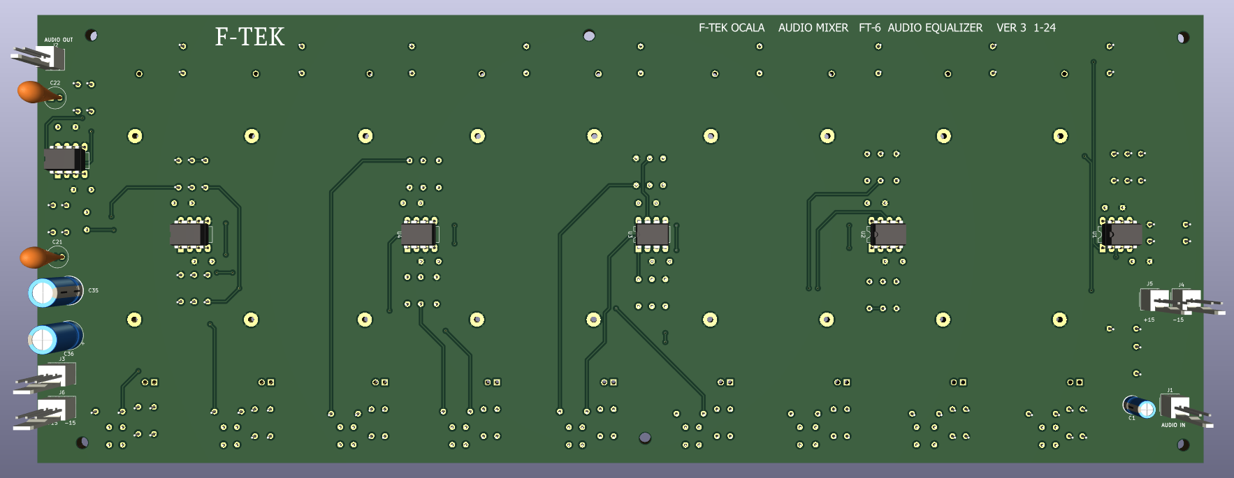
I have finalized the board design for the Equalizer.
One item I neglected to mention previously was the bypass switch.
Below is the diagram of the switch.

And the final Board version.


.
.
We are progressing.....As the boards are almost ready to ship

Here is the board direct from China.

We will begin by adding all the power components. Then, we can apply power and verify its functionality.

The two beige connectors, one goes to the power supply, the other will go to the other board. (right channel)


Next, I move on to the terminals and jacks.
Then comes the resistors and the remaining capacitors.

I have positioned one of the potentiometers to ensure it fits perfectly. I will solder it in later.

Now that all the resistors are installed, we should proceed with adding the small capacitors.
OK, let's move onto the potentiometers.


Now we can add the LEDs, and power it up. NOTE: We have NOT added the chips yet.

Everything OK? LEDs are showing power? Check for the voltages at each chip location.
All is well?
Now we can add the chips. The 4558 chips were a tad 'noisy', so I went with the NE5532 chips.
Now power it up and see if the imbedded smoke stays INSIDE the chips. I had a 4558 get blown to bits. I thought we had a board disaster, but it turned out to be a defective chip.

We hook up the audio goes ina and comes outa.
Let's find an audio source and give it a try.

And it works!!!!
It's a very short video, as Blogspot has a minimum size for videos.
We now have an audio equalizer. Well, one channel at least.
We need a break.

This is impressive. But we are not done yet, we need do the RIGHT channel.
I did the right channel a bit different. I started by placing ALL the resistors.


And the Audio Filter capacitors for each audio band.

Here I have taped down the 8 pin IC sockets, so I could turn the board over.

I only solder two pins. (each corner) then turn the board over. I can adjust any of the sockets if needed.

Now I can finish up the sockets.


Are we done....... Not quite... There is more thing to be done.
We need to design and construct a cabinet for this project.
And we can remove parts from the prototype that we can use later.
I will run this board (as I did the other) for 24 hours
I am constructing a 'meter bridge' that will sit on a shelf above the mixer. I believe that is an appropriate location for the equalizer. But more on that at a later time.
I think we will leave things as they are for now and make the cabinet as Part 3.

I believe that next time we will complete the Digital Clock Project with a nicely designed cabinet that will be placed on the dresser across the room. I have realized that the digits are large enough be read from that far away. Then we will jump back in the shop and make some turned bowls out of some interesting wood.
But first I need to clean the shop.

Be sure to visit some of my other blogs:
AROUND THE KITCHEN - SEE WHAT I COOK
BRIARWOOD - YOU CAN READ MY NOVELS
AUDIO CONSOLE - WHERE I AM BUILDING AN AUDIO MIXER
DISCLAIMER The information contained here is for ENTERTAINMENT purposes only. Working with woodworking tools can be dangerous. The user of these tools should have a basic knowledge of woodworking and be familiar with the proper use and safety precautions associated with these tools. Always wear appropriate personal protective equipment, such as safety glasses, ear protection, and a dust mask. Always use the tool in accordance with the manufacturer's instructions and guidelines. Always maintain a safe and organized work area.

God Speed Mother Nature


No comments:
Post a Comment