Thank you for joining us today at Fresh's Workshop. If this is your first visit, welcome! If you're returning, we appreciate your continued support.
This is the spot where we build and repair all kinds of cool stuff, along with making a ton of saw dust. (Man Glitter.)
During our last session in the Workshop, we showed you Part 2 of our Stereo Equalizer project.
Before we begin today's project, let's take a moment and talk about shop safety:
Be sure to read, understand and follow all of the safety rules that come with your power tools. Knowing how to use your power tools properly will greatly reduce the risk of personal injury. And remember this, there is no greater safety rule than to wear safety glasses.
We have returned to the shop so we can complete our Digital Clock for the Bedroom project.
Previously, we constructed the Power Supply, the Display Board, and main clock board.
If you missed that part, you can view it HERE.
Now, we aim to finalize everything with a controller board and an elegant cabinet.
First, the controller.
Its operation is quite straightforward. We require 5-volt pulses to reset the seconds and increment the minutes and hours. Although this sounds simple, I encountered issues in getting it to count one digit at a time due to switch bouncing. After numerous unsuccessful attempts, the problem was resolved by using a 'Switch Debouncing' IC. By feeding a ground through a switch to the input of the IC, a clean pulse is obtained. This clean pulse will be used for the hours and minutes count.
The issue we faced was that the output of the debouncing chip is a ground, whereas we need a positive pulse. This problem was resolved by utilizing a CD4049 Hex Inverter chip. The CD4049 takes an input and converts it to its opposite state. In other words, a ground pulse on the input yields a positive on the output. And vicey versey.
The schematic.
How it works. We will use the 'minutes' for this discussion. A ground is switched by SW2 feeding it to the input of U1B. The pulse is cleaned up by the chip and the chip output then goes to U2B. The ground pulse is converted to a logic + and this goes to J1 Pin 2. This + pulse is then sent to the minutes chip on the main board and the minutes is increased by a count of 1.
Here is the board. (TOP & BOTTOM)The top holes are for the three switches. Hours/Minutes/Re-set.
I need to build two of these for the Ham Radio Clock project and one for the Digital Bedroom Clock.
I think for this build we will use regular momentary toggle switches.
Let's put the board together and see how it works.I meant to move the 8-pin chip to this side but forgot when I was designing it. But it will function just fine with this configuration.And here is one unit I put together for the Ham Radio Clock.
So, the controller has been tested and works well.
Now we can think about making a case.
NO, not that kind of a case.For the cabinet, I searched around You Tube looking at other clock makers and their choice of cabinets. The general consensus was to show off your work.
I settled on this idea from 'Tinkering Jim'.
This cabinet combines my two passions: electronics and woodworking. (Additionally, I have a deep appreciation for my wife, Louis Grizzard, and SEC football.)I am considering a maple base with purple heart corners. I will incorporate clear Plexiglass for the back, top and sides. I have some red Plexiglass that I believe will work for a front.
(Actually, it was 1/2 inch too small, so I went to my friends at AMAZON.)
Let's get to the shop and make some sawdust.
I could spend hours at a drawing board planning this cabinet, OR I can make a prototype and adjust it as needed. Then we can get out the Maple and Purple Heart.
Step one was to secure a large piece of spare plywood and cut a groove for some 1/4" plexiglass. (I did not do this step in the final version.)
Then we took a spare blank display board and taped a display chip plugged into a socket. (simulating the real board)
Then we can judge where the display board will be installed.
Now, let's mount the display board on the base.
We possess substantial quantities of metal pieces that can be modified for this purpose. I am unaware of the intended use of these items. I acquired several pounds of them at a surplus sale thirty or forty years ago. (Ed McDade, please take note)
But first, we need to get rid of that little metal 'ball' on the end.We used a scrap piece of 2x4 and drilled a hole the size of the 'ball'.
I placed the ball inside the hole and using a center punch, I punched the ball into the hole.Now, we need to make a 90-degree bend, using my metal brake from Harbor Freight. (According to their web site, it is no longer available)
I placed the part in the middle of the brake and placed the bar on top. A clamp at each end, and we are ready to bend. We got out our 4-40 nuts and bolts and mounted the display board.
For the main clock board, we used a spare clock board and mounted it using some stand-off mounts.
Now the power supply gets the same treatment. (We ended up mounting the Power Supply in the vertical plane)
Now we turn our attention to the corners. They are the cornerstone of our project. (You can 'groan' if you need to.)
Using spare plywood scraps, I cut grooves to accept the 1/4 " and 1/8" plexiglass.
Note: The Plexiglass I am using here is some used Plexi that I had stored in my Plexiglass drawer. Although it's scratched, it serves well for temporary use.
We are making good progress on a prototype cabinet. Now that we have 4 corners, we need to cut them down as they are a bit too tall.
Now we have a good height for our case. We can now move on to making our final version. I made a few adjustments based on the experience we had with the prototype case. I will make the base a bit larger, and I will set the corners all in the same direction. I also found some 1/4-inch plexiglass for the sides and back. But first let's glue up some Maple and cut the Purple Heart for the corners.
Let's set this aside to dry and cut the Purple Heart to size. When cutting strips ALWAYS use a 'push stick.'
To cut the grooves, set the saw height to about 1/4" depth. Run a cut down the center, then flip it around 180 degrees and repeat the cut. Your groove is now in the exact center of the board. (You can also use a router table for this step) If the cut is too small, move your saw fence in towards the blade (NOT TOO MUCH!!) and cut again. Turn the piece 180 degrees and repeat the cut. Repeat until the Plexi fits into the slot.)
Once the grooves are cut, check the fit using some plexiglass scraps.
Grooves look good, let move onto the base. Here, I need to scrape off some glue and start sanding. As you sand, occasionally wipe the board with Mineral Spirits. It will show you where you need to sand. With the first round of sanding completed, let's trim this to size.
Using the shaper, we add a small 'round over' on the front of the cabinet. You can also use a router or hand sander. Now, we can draw out where the corners will live and cut some plexiglass. We will keep the protective cover on the plexiglass until we are finished with the cabinet.
The round over portion is at the top.
Using the Band Saw, we can cut the RED Plexiglass for the front. And the CLEAR Plexiglass for the back and sides. Now let's see how it all comes together. Looks good!!!! I need to trim the plexiglass to fit perfectly, then we can check out the fit with the boards I'll be using and finalize their location. We also have to drill holes in the side for the controller, as well as holes in the back for the set switches and the power input jack.
But first, we need some holes on the bottom to accept the corners.
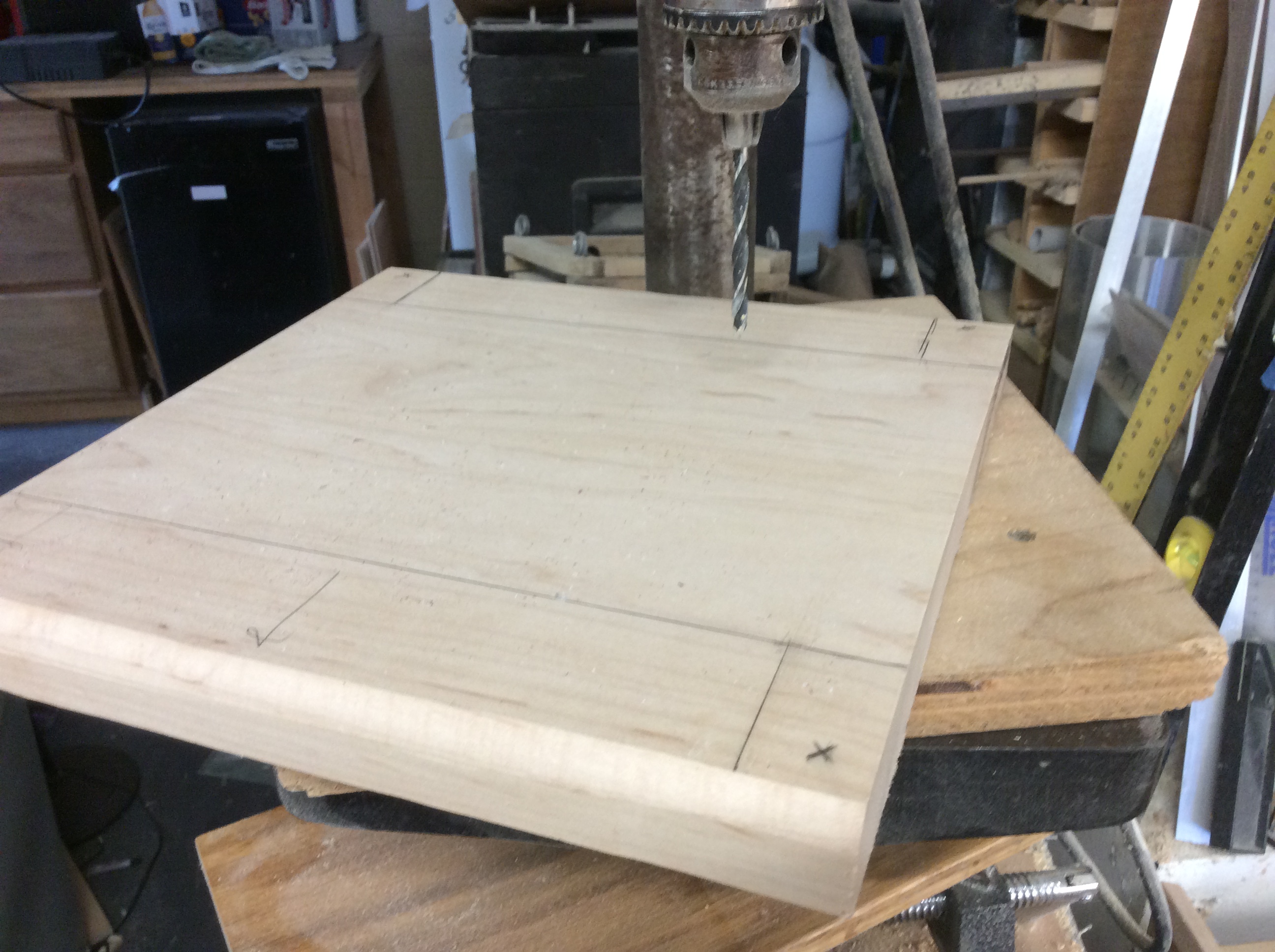
Here I have marked the location of each hole.
At the drill press. (I have already marked the hole locations with a punch) I have also drawn an arrow pointing to the front. You need to ensure that you always know where the front is when adding your corners.
Four holes.
We need to counter sink for the screws on the bottom. We also need to sharpen our planer blades.
Placing a screw in the hole, we carefully mark the corner. Set the corner in place on top of the screw and tap the corner down against the screw.
Now drill your pilot hole. (Purple Heart is a very HARD wood.)
Now we can mount the two front corners. I did not glue them, as I will be removing them later for finishing. Front is done. Onto the back.
Helpful hint. You can use the plexiglass as a guide for the last two corners.
Let's look at board placement. I made some brackets for the bottom of the display board as well as the top. I did not bend the top brackets (See above on how to make the brackets) Here is where I decided to change the power supply mounting scheme. Here is the mounted power supply Placing the main board to mark for hole location.
I drilled four holes to accept the plastic stand offs. We will start by glueing them in place with epoxy. If that does not work well, we will drill the holes all the way through the bottom and use bolts. I also drilled holes for the switches and power jack located on the back of the clock.
Notice that the plexiglass on the back is not as tall as the one on the front. This is because I wanted a bit of ventilation above the heat sink.
Now we add the controller board.
Don't worry, you'll get a better view in a bit.
Let's let it run for a bit before we continue.
Time for a break.
So, I have been staring at this project for a while, and something seems a bit 'off'.
Yes, I see it now. I need to round over the corners and add some 'side' strips.
Now let's take it all apart and finish the corners. We start by rounding off the corners. Always start with a test piece.Then finish up on the belt sander. It's a bit hard to see but here I have tested the piece with some Mineral Spirits. When I removed the corners, I marked each with a number and a corresponding number on the bottom of the base. This will ensure that I get it right when I re-assemble the cabinet. Now we can cut out the edge pieces from the Purple Heart. Apply some glue, then clamp it up.
Now that the glue is dried, (the next day) we need to use the shaper and do some rounding over. And now some serious sanding is needed. We sanded and sanded. First with the belt sander, then with the orbital sander using 180 grit then 220 grit paper. Now we can lay down our first coat of Sanding Sealer.
I use Minwax Sanding Sealer.
First lay some paper on your table. You need to 'elevate' your project. I used some nails in a scrap piece of wood, and a couple of dowels.
Don't forget to wear gloves. I put on 4 coats of sealer with a light sanding after each coat.
Then I sprayed on 4 coats of Lacquer.
And buffed it all out with some 0000-steel wool.
Now we can mount all of our boards, switches, and power jack.
Here we are wiring the switches.
Notice I replace the stand-offs with plastic ones. The first ones I used shorted the board. Duh!
Now we need to shorten the power cables I used on the prototype.
And one of the cables to the display was a bit too long, so I shortened it. You do not need a professional crimp tool for this. I used a small vice for years.
We finish up the main construction by cutting the top Plexiglas to size and mounting it to the top. Drill some holes on each corner.
You will have to remove the protective covering for this step, so BE CAREFUL not to scratch your panel.
Using your ruler, center the panel.
Drill the four holes through the Plexi and into the Purple Heart corners.
Before you mount it in place, lay on some felt cut to size on the top of the corners. Thus, covering up the slots in the purple heart. (I told you that I had a plan.)
And trim it up.
And Bob's your uncle.
For the bottom of the case, you can use some rubber feet or just some more felt. I am still deciding.
All buttoned up and sitting on our dresser, along with a cool night light I made some 30 years ago. We may re-visit that project someday.
Wow, this was a fun project that was spawned by another project. It was fun to build, and I can actually see the digits from across the room. It surely will give me years of service. Best of all, it was made with left over parts from my other clock projects. The only expense was the RED plexiglass for the front, and I had to buy a new piece of clear for the top. It was also a great way to experiment with a cabinet before I make one for the Ham Radio Dual Clocks. I believe that next time we'll jump back in the wood shop and make some turned bowls out of some interesting wood. Or is it really wood? We will see. Then we will return to the bedroom and make a shelf to go under our wall mounted TV.
Thanks for joining us, and we hope to see you again in the shop.
Be sure to visit some of my other blogs:
DISCLAIMER The information contained here is for ENTERTAINMENT purposes only. Working with woodworking tools can be dangerous. The user of these tools should have a basic knowledge of woodworking and be familiar with the proper use and safety precautions associated with these tools. Always wear appropriate personal protective equipment, such as safety glasses, ear protection, and a dust mask. Always use the tool in accordance with the manufacturer's instructions and guidelines. Always maintain a safe and organized work area.
And another shot from the Burton Cummings concert in Clearwater. What a blast it was to see him and his band live! He really brought back those memories of the GUESS WHO.


No comments:
Post a Comment